I have a toshiba laptop that one day decided to just stop working. No amount of hardware inspection revealed why it had died.
The only choice I had left was to scrap it for parts.
One of the interesting modules I got was a 640x480 webcam. Inspired by this instructables guide, I set out to make my own.
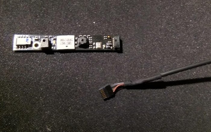
The front part of the module didn’t seem to have any useful information. Searching the camera’s model number also did not turn anything.
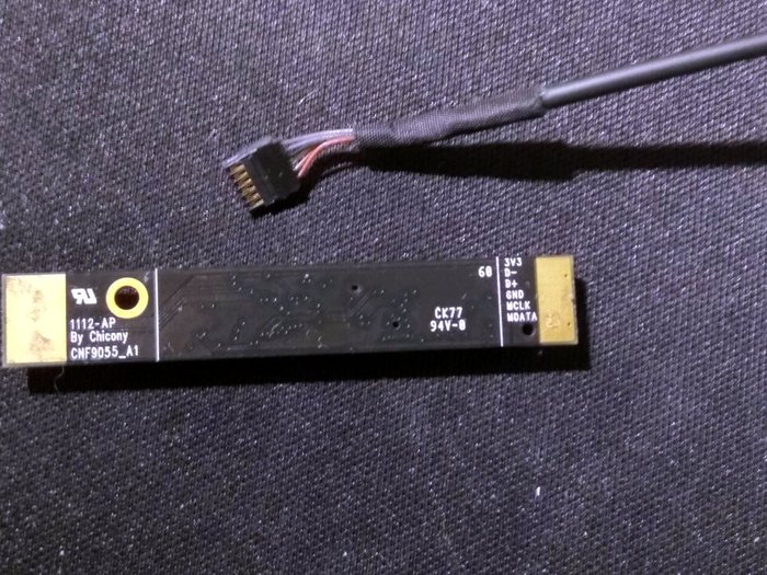
The back part of the module though showed a pinout which translated to:
- 3V3 - Red
- D- - Brown
- D+ - White
- GND - Black
- MCLK - Grey
- MDATA - Cyan
MCLK and MDATA refer to the module’s microphone and do not interest us (for now).
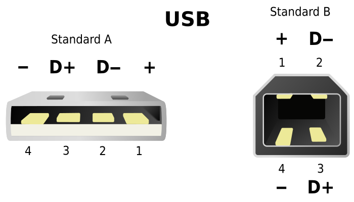
A normal usb connector has these connections:
- +5V - Red
- D- White
- D+ - Green
- GND - Black
The pinouts seem very similar and almost as easy as soldering one end to the other.
There is a “slight” voltage difference between them and connecting them would probably fry the board.
The 1N4007 diode
As you can see from this specification sheet the forward voltage of this diode at 200mA is 0.8V. If we put 2 diodes in series that accounts for a voltage drop of 1.6V.
Finally, considering the camera module draws between 150 mA and 250 mA (blind estimate) that should place our resulting voltage in the range of 3.3-3.5V.
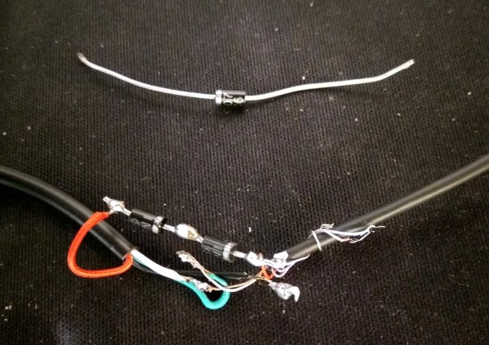
The Setup
After cutting the mini-usb part off a mini-usb to usb cable, I proceed to solder the corresponding cables D- to D-, D+ to D+, GND to GND and 5V to the 3v3 with the diodes between them (the strip part of the diodes (negative/cathode) closer to 3V3).
 Just after having finished soldering. Right- USB, Left- webcam.
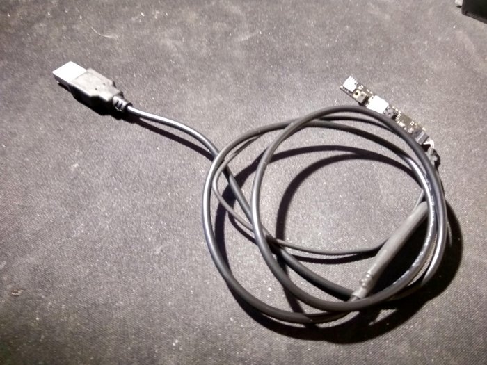 Final product. Hiding the terrible soldering joints with shrink tube
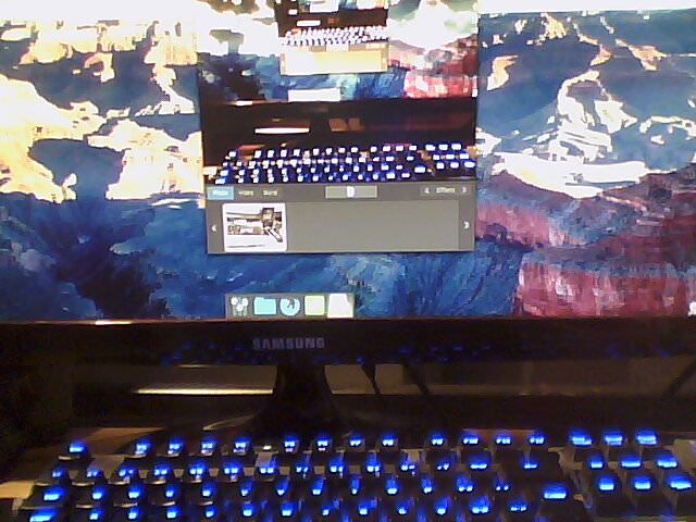 It's alive!
The computer immediately recognized the webcam and I was able to start recording using cheese.
The webcam has a very poor recording quality but it’s still better than throwing it away.